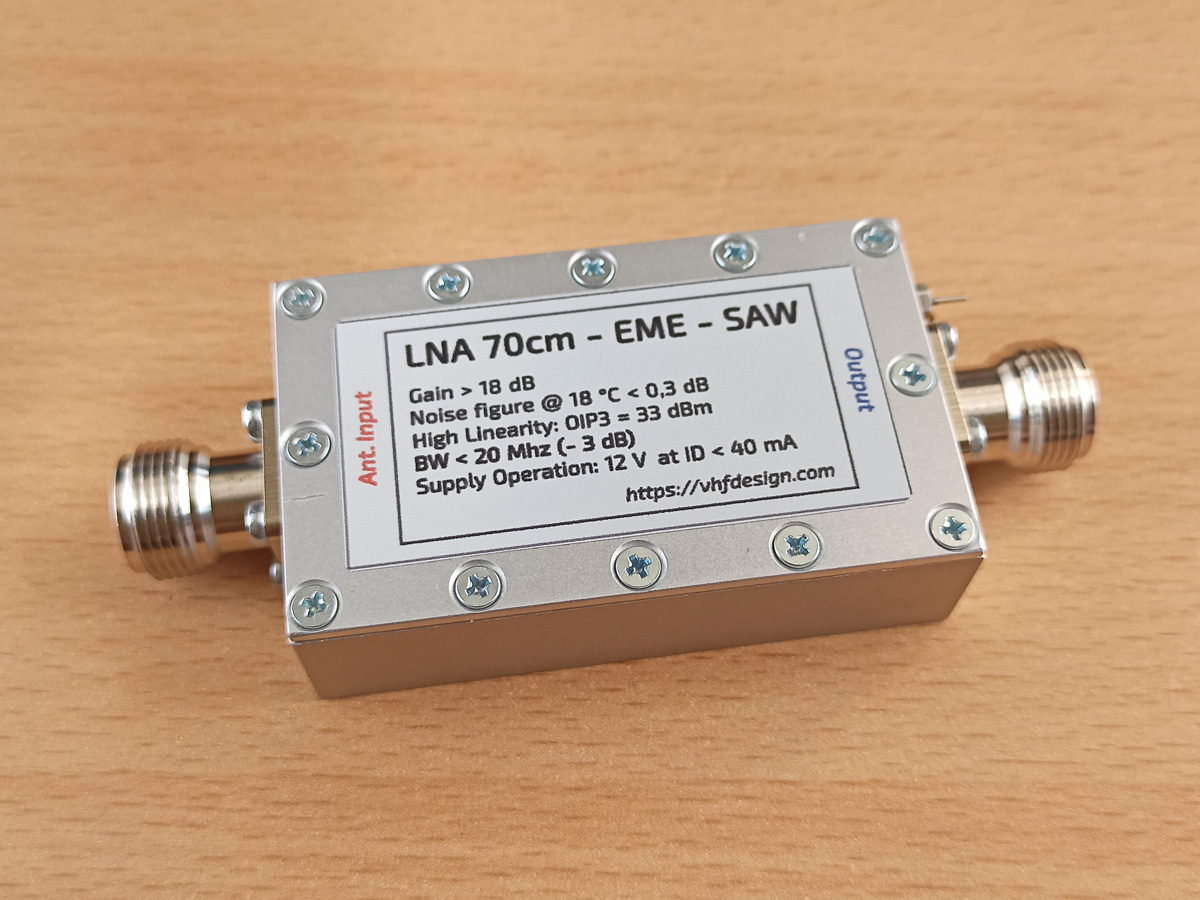
Update from 15.10.2016
LNA with 73cm band filter is also available. Technical specifications are the same as for 70cm band solution.
During the search of the new E-PHEMT for EME LNA at 70 cm frequency range, it was paid attention to E-PHEMT SAV-541+
LNA simulation
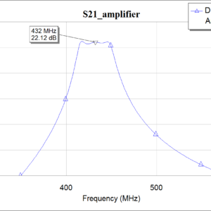
E-PHEMT SAV-541+ Fmin = 0.06 dB at 430 MHz – in S2P file we can find 0.5 GHz, Fmin = 0.076 dB. Simulation of the LNA schematics approves NF < 0.16 dB. Band pass filter is designed with MPL inductances. The filter bandwidth (by the level of -3 dB) is less than 40 MHz (BW < 40 MHz). The LNA and filter schematics, that is used in design environment are shown on Fig 1.1 and Fig. 1.2


The results of the LNA simulation (Fig. 2.1, Fig. 2.2, Fig. 2.3, Fig. 2.4)
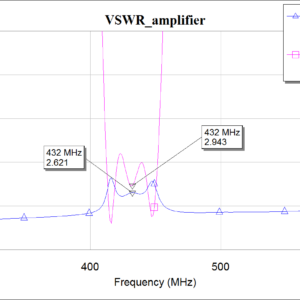
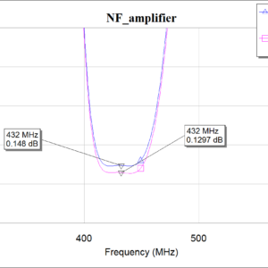
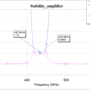
The distinctive feature of the LNA, which is based on the transistors – high VSWR on the input. This project is not unique from this point of view – VSWR < 2.6. For operation on the air the high input VSWR is not so critical, but it may cause NF measurements errors. Thus, it’s not worth to rely on the NF measurements because of the high VSWR, even if you use high precision NF analyzer. The main error of the high precision NF analyzer is around +/- 0.1 dB, but the error due to high VSWR can achieve 0.3 dB and even higher. From the practical point of view it’s worth to measure noise of the sun relative to the noise of the «cold sky», in the «quiet» air, by using antenna with high back hemisphere suppression, with lifting angle that allows decreasing the noise of the earth.
LNA-70cm-SAV-541+ design features
LNA consists of the matching transforming circuit, E-PHEMT SAV-541+, low noise integral voltage 5V type LP2992 regulator, 3rd order band-pass filter, biasing transistor circuit and power supply circuit by feeder reduction.
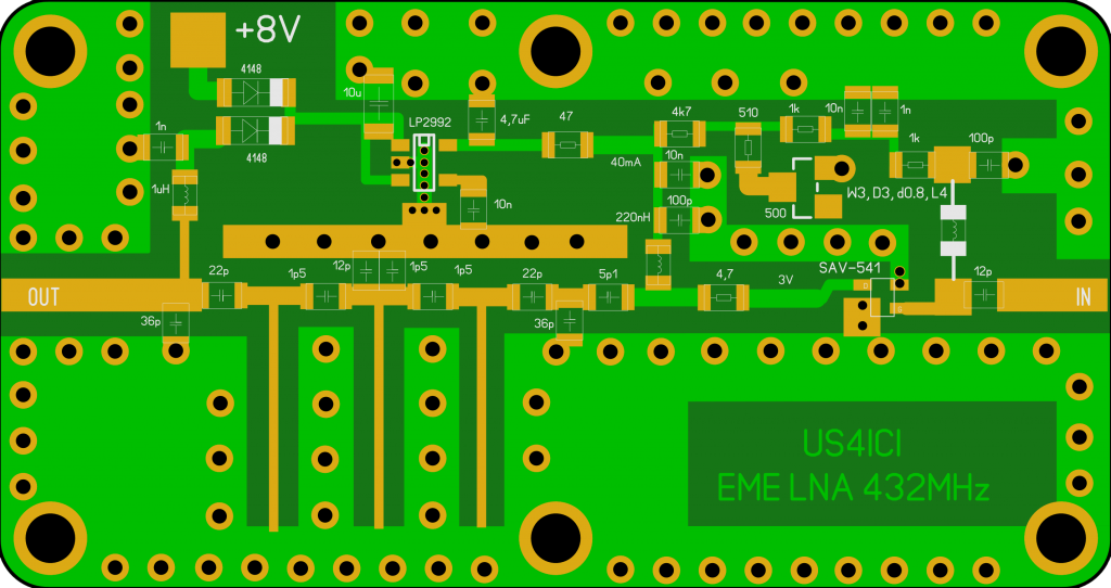
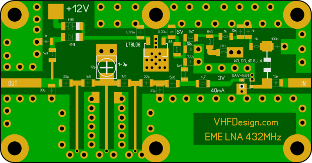
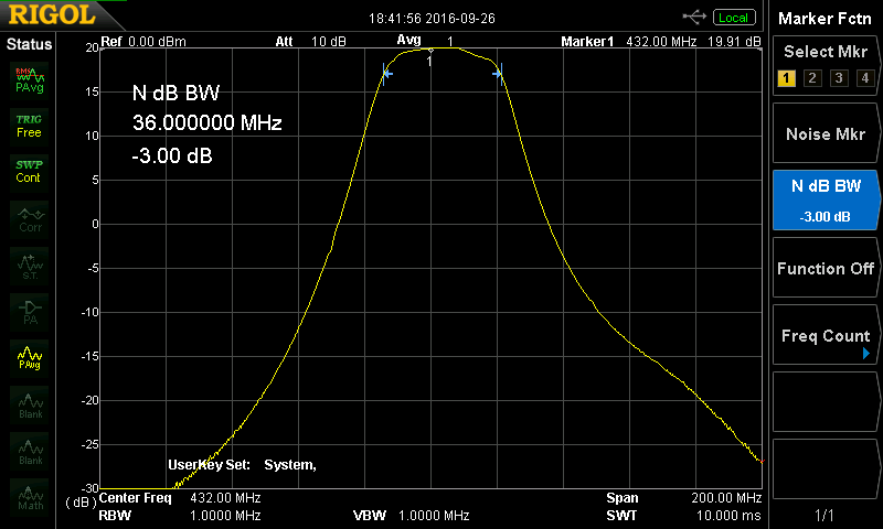
PCB sizes are 60×32 mm, it manufactured with 1mm thickness FR4 substrate material, plated vias and mask. MPL inductances of the filter are based on the pieces of the microstrip lines. BW (-3dB) < 40 MHz. Blocking bandwidth attenuation is -80 dB at 144 MHz. PCB layout is shown at Fig. 3
The housing of the LNA is manufactured from aluminum plate D16 by milling on CNC machine. There are different options of the housing for the N-type socket and SMA socket connectors. Power supply is designed through the feeder or capacitor that mounted on the surface of the housing. Power supply voltage is 8 – 13 V.
Measurements results are shown below:
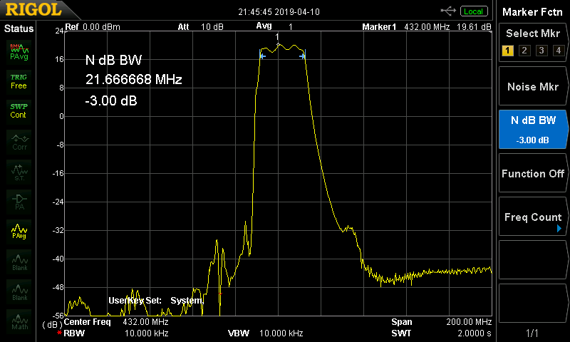
Conclusion
The designed LNA was tested by the leading ukranian ham radio EME amateurs UT5DL, UX0FF. The reviews can be found here.
Compared with the LNA based on chip SPF5122z, the designed LNA is inferior in dynamic range, but much better by noise figure. The designed LNA is recommended for EME tests and everyday work in the air in the absence of strong interference.
LNA 70cm EME SAV541 SAW filter N-female
| Name | LNA-70cm-EME-SAV541-SAW-N-female |
| Based on | SAV-541+ |
| Gain | > 18 dB |
| NF | < 0.3 dB at 432 MHz |
| OIP3 | 33 dBm |
| Filter BW (-3 dB) | < 20 MHz |
| Supply operation | 12 V & 40 mA |
| Impedance | 50 Ohm |
| RF connectors | N-female |
| Dimensions | 72 x 43 x 20 mm (w/o connectors) |
| Weight | 0.15 kg |
| 1 | x | LNA-70cm-EME-SAV541-SAW-N-female |
General inquiries:
![]() admin@vhfdesign.com
admin@vhfdesign.com
Technical support:
![]() us4ici@vhfdesign.com
us4ici@vhfdesign.com
Check the availability:
https://vhfdesign.com/kits/list
