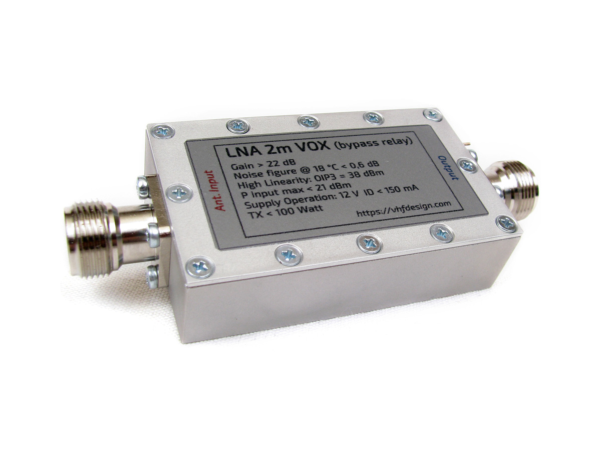
In this project we are present a new version of the LNA with bypass relays and RF VOX. This construction is different from the previous version. It has different bypass relays (up to 100 Watts) and RF transceiver control circuit. Area of the application is utilization of the FM transceivers and radio stations (LPD, PMR). It’s possible to use LNA for civil LPD frequency band (433 – 435 MHz) and PMR frequency band (446 MHz) with usage of the feeder and stationary remote antenna. The solutions for other frequency ranges (4m, 2m, 1.25m and 70cm) are also available.
The LNA is manufactured based on PGA-103+ Mini-Circuits Monolithic Amplifier with high dynamic range.
RF VOX is designed for protection from accidental power supply to the LNA output. Because of RF VOX it is possible automatically switch LNA in TX mode (till 50 Watt) for the FM application. For the owners of the portable FM (LPD, PMR) radio stations it is sufficient to connect LNA to feeder and turn on power supply. RX/TX switching is automatic.
LNA simulation
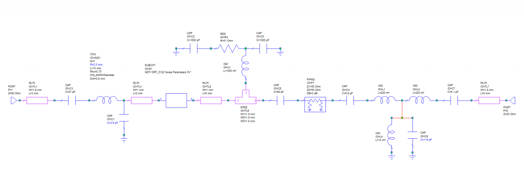
Unfortunately Mini-circuits did not provide us with S2p files for the MMIC PGA-103+. Simulation was performed for the analogue MMIC SPF5122z.
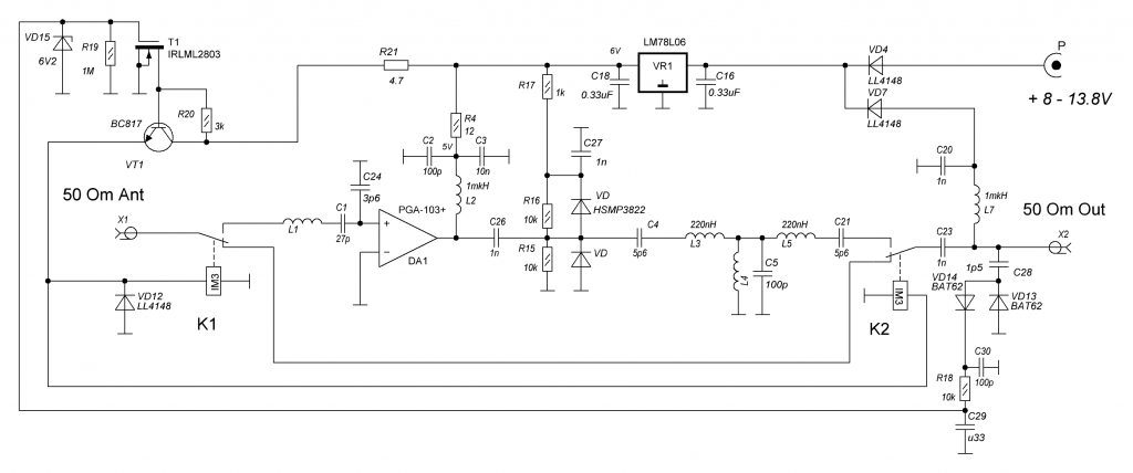
Schematic of the LNA-2m is shown on Fig. 1.1 and Fig. 1.2

Simulation results based on LNA-2m (Fig. 2.1, Fig. 2.2, Fig. 2.3, Fig. 2.4)
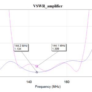
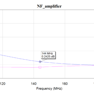
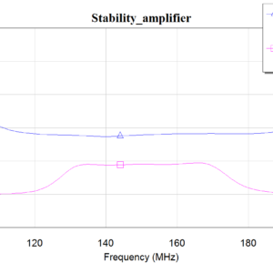
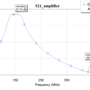
According to the simulation results: NF < 0.3 dB, VSWR on the input and output is less than 1.5. Gain equals 23 dB. LNA is absolutely stable.
LNA 2m design features
LNA consists of the matching transforming circuit, MMIC PGA-103+, 6V voltage regulator, band-pass filter, bypass relays AXICOM IM2, RF VOX elements and power supply circuit by feeder reduction (Fig. 3). Values of the input circuit elements and band-pass filter depends of operating frequency range. Power supply of the LNA is 12 V DC. There is opportunity to connect power supply using RF feeder from transceiver or using power supply injector.
Block-diagram of the LNA is shown on Fig. 3
LNA DC power supply and commutation requirements
When DC Power OFF, LNA works in «bypass» mode — the transmitter power passes through the LNA to the antenna. LNA is not active in «bypass» mode (during TX).
When DC Power ON, LNA become active (during RX).
For proper LNA commutation you should remove DC Power from it before transmitter power comes to LNA Output. If switch to TX without LNA DC Power OFF — switching will occur via RF VOX. You should understand that in this case (RF VOX triggered) relays will be switched under the load. Because of this, transmitter power should not be greater than 50 Watts. VOX has a delay while going to RX. Working with LNA VOX without power commutation in CW and SSB modes is not recommended. In general, It is better to leave the VOX feature just for an extra protection if random RF power will accidentally come to the LNA Output.
LNA-2m-100W-RF-VOX was successfully tested operating with 100 Watt transceiver IC910H. However it is not recommended permanently using RF VOX with this big power. Bad VSWR of the antenna can cause some issues with relay pins.
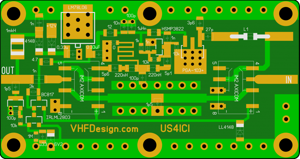
The PCB of the LNA has 60×32 mm dimensions. It is manufactured with 1 mm thickness FR4 substrate material with plated via holes and soldering mask. Inductances of the band-pass filter are high quality SMD 0805. The input inductance is designed with 0.8 mm wire.
LNA-2m PCB is shown on Fig. 4
AFC is shown on Fig. 5.x
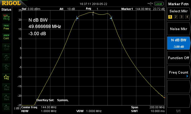
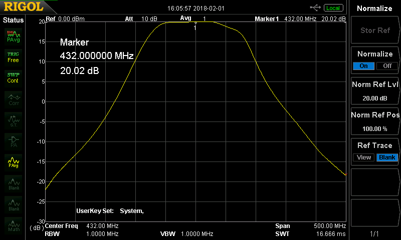
The housing of the LNA is manufactured from aluminum plate D16 by milling on the CNC machine. It has N-female input and output connectors. Power supply is designed through the feeder reduction or capacitor that mounted on the surface of the housing.
Conclusions
Easy installation while working without PA with transceiver or FM radio station. Protection against accidental flow transmitter output power to the LNA enhances operational reliability. RF VOX helps to work without RX/TX switching in FM mode. It’s possible to use LNA for civil LPD frequency band (433 – 435 MHz) and PMR frequency band (446 MHz) with usage of the feeder and stationary remote antenna.
LNA 2m VOX N-female
| Name | LNA-2m-VOX-N-female |
| Based on | PGA-103+ |
| Pmax TX bypass | 100 Watt (50 Watt RF VOX) |
| Gain | > 22 dB |
| NF | < 0.6 dB at 144 MHz |
| OIP3 | 38 dBm |
| P input (max) | 21 dBm |
| Supply operation | 12 V & 150 mA |
| Impedance | 50 Ohm |
| RF connectors | N-female |
| Dimensions | 72 x 43 x 20 mm (w/o connectors) |
| Weight | 0.15 kg |
| 1 | x | LNA-2m-VOX-N-female |
LNA 70cm VOX N-female
| Name | LNA-70cm-VOX-N-female |
| Based on | PGA-103+ |
| Pmax TX bypass | 75 Watt (50 Watt RF VOX) |
| Gain | > 20 dB |
| NF | < 0.8 dB at 432 MHz |
| OIP3 | 38 dBm |
| P input (max) | 21 dBm |
| Supply operation | 12 V & 150 mA |
| Impedance | 50 Ohm |
| RF connectors | N-female |
| Dimensions | 72 x 43 x 20 mm (w/o connectors) |
| Weight | 0.15 kg |
| 1 | x | LNA-70cm-VOX-N-female |
General inquiries:
![]() admin@vhfdesign.com
admin@vhfdesign.com
Technical support:
![]() us4ici@vhfdesign.com
us4ici@vhfdesign.com
Check the availability:
https://vhfdesign.com/kits/list
