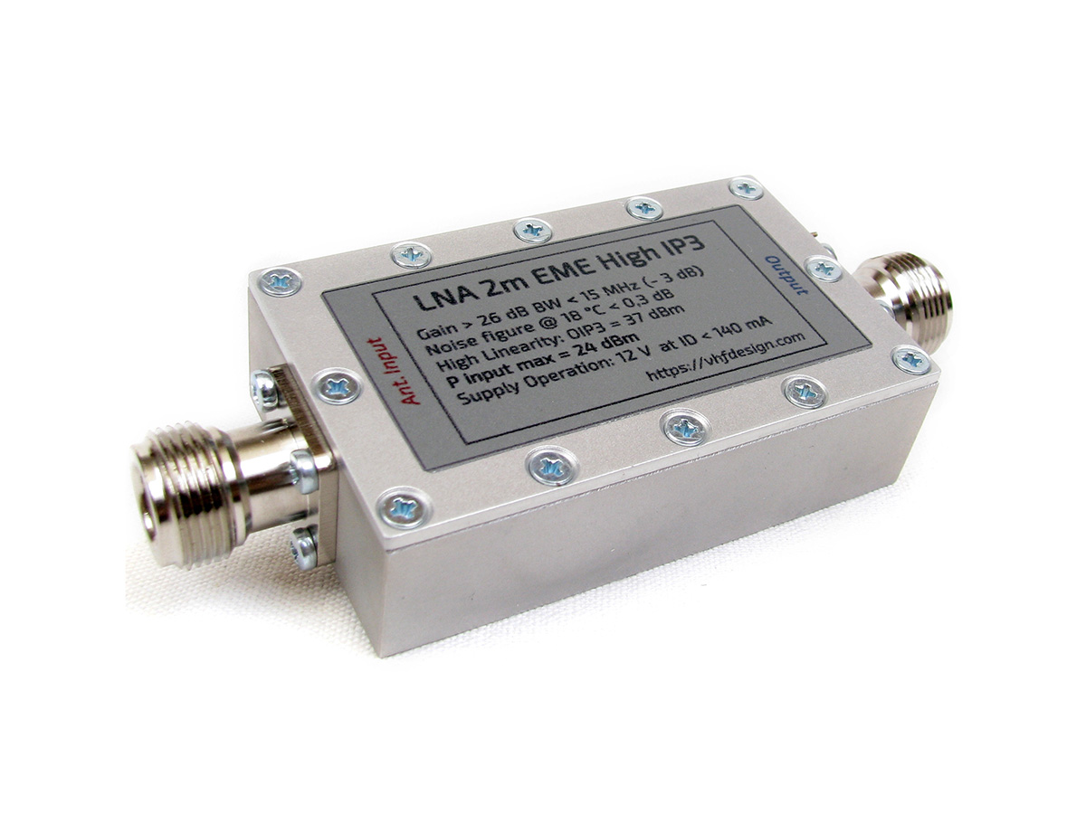
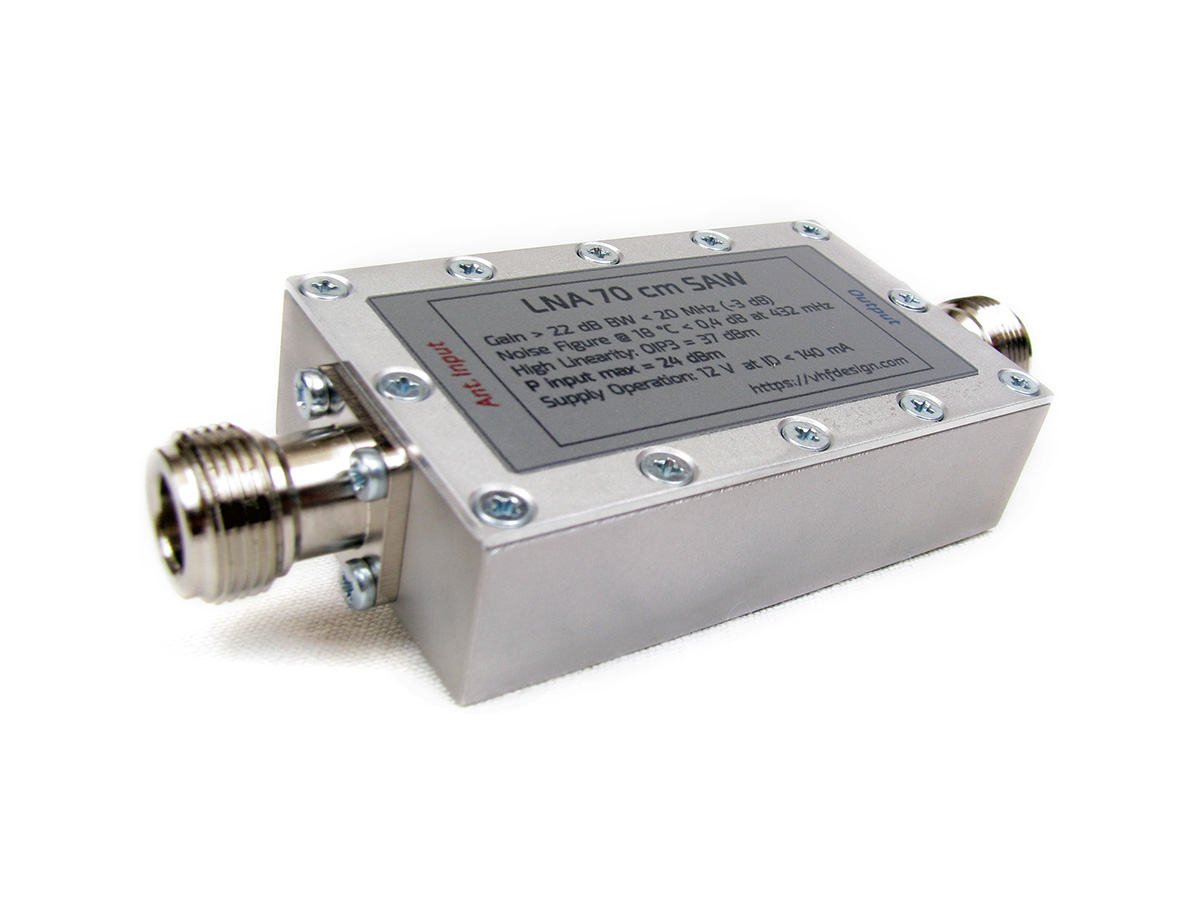
In this project we created all-purpose LNAs for all QSO types (Tropo, Contest, EME, etc.) for 2m and 70cm bands. LNA was designed using ATF-531P8 E-pHEMT with High IP3 (37 dBm). Noise figure is much better than on PGA103+ or SPF5189z for 2m band (< 0.2dB). ATF-531P8 E-pHEMT is more reliable than low power ATF-54143 (SAV-541+). The location of the band-pass filter on LNA’s output allows to suppress the FM band and adjacent bands that close to FM band.
The LNA simulation
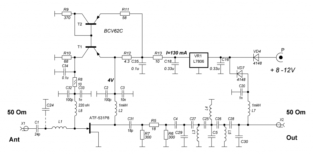
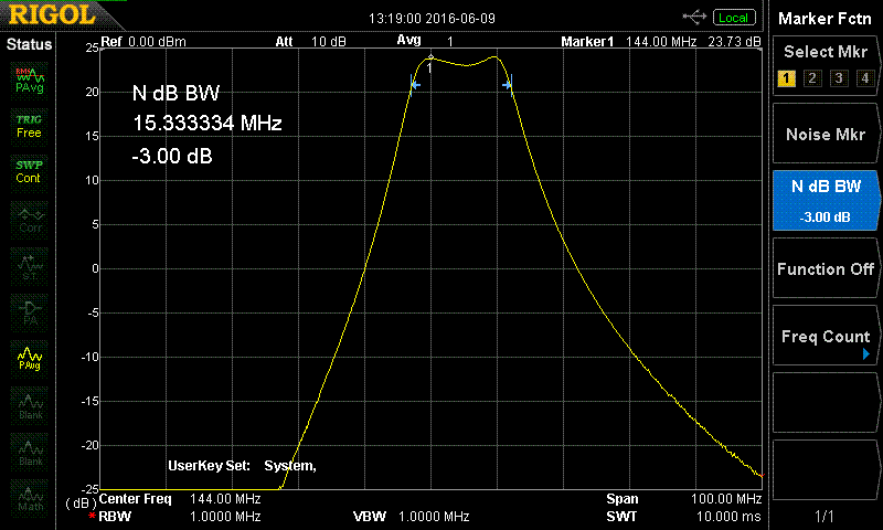
According to S2P files of the ATF-531P8 with drain-source current range 75-135 mA, noise figure has very low values. Simulation of the LNA 2m schematics validates that NF < 0.14 dB (Fig.2). Band-pass LC filter is manufactured with frameless inductances using copper wire. The -3dB level bandwidth is approximately 15 MHz. LNA and filter schematics is shown at Fig.1.1 and Fig.1.2.
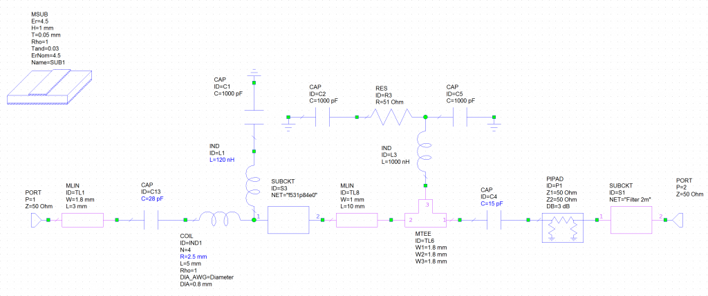
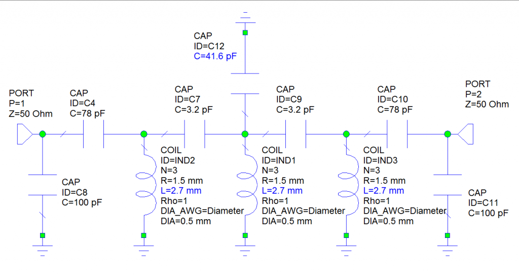
Simulation results (Fig. 2.1, Fig. 2.2, Fig. 2.3, Fig.2.4)
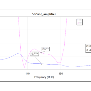
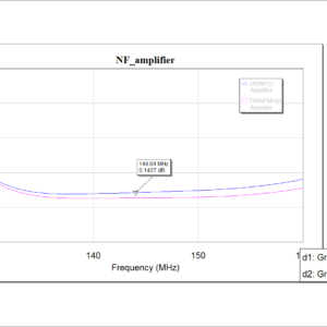
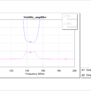
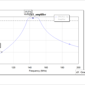
VSWR at LNA input does not exceed 1.5. The gain equals 27 db, absolutely stable.
LNA design
LNA consists of matching-transforming circuit, E‑pHEMT ATF-531P8, integral voltage stabilizer 6V type L7806, attenuator -3dB, third order band-pass filter, stabilizing biasing circuit, power supply circuit by feeder reduction. Values of the electronic components in matching input circuit and band-pass filter depends on frequency range (are not defined in figure). The drain voltage should be set equal to 4V with drain-source current equal to 135 mA for adjusting E‑pHEMT by the direct current. LNA power supply voltage range is 8-12 V. You can supply it through the feeder (if your transceiver supports this feature) or via pass capacitor on the LNA body.
PCB board material – FR4, 1 mm, dimensions 60×32 mm with copper metallization and mask. Filter inductances are fabricated with 0.5 mm copper wire on the 2.5 mm core. Filter configuration is performed with inductance winding pitch. PCB for 2m (Fig. 4.1) and 70cm (Fig.4.2) are shown below:
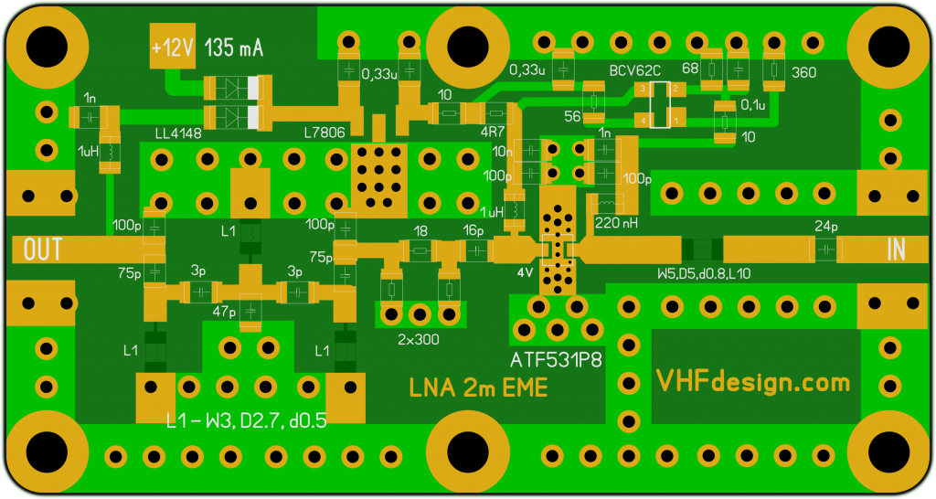
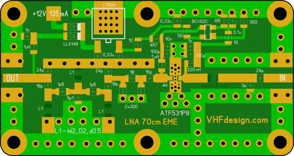
The housing of the LNA is manufactured from aluminum plate D16 by milling on CNC machine with N-female connectors by default. We can install SMA-female or other connectors by your request but manufacture will take more time. Power through the pass capacitor on the LNA body or through the coaxial feeder (if your transceiver supports this feature).
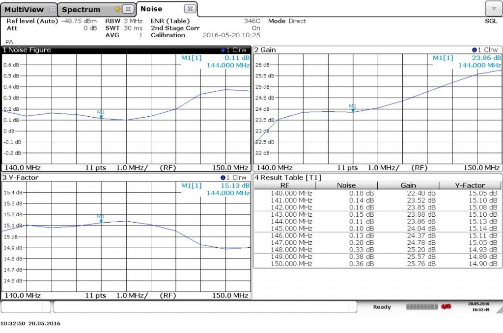
Frequency dependence of the noise figure was measured using R&S®FSW Signal and Spectrum Analyzer (Fig. 5)
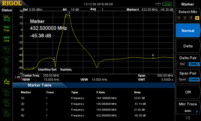
AFC graphs in narrow and broad bands are shown on Fig. 6.1, Fig. 6.2, Fig. 6.3. At the figure 6.1 in the wide band the second marker depicts the suppression of the VHF FM broadcast band (more than -70 dB). The 4th marker depicts the suppression of the band at 430 MHz (approximately -70 dB).
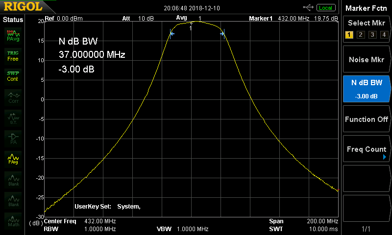
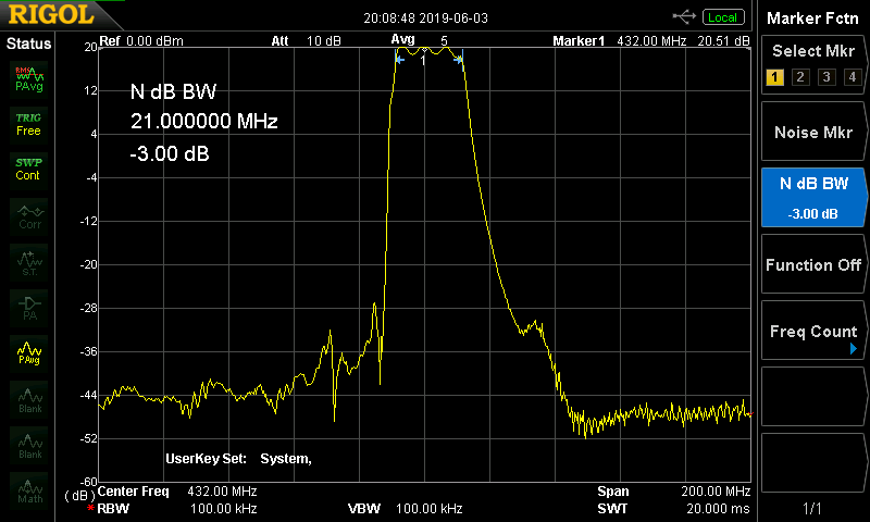
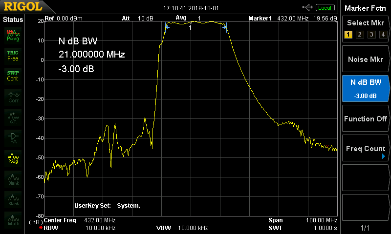
LNA 70cm simulation. Noise figure in this band is a little bit worse. The VSWR is rising up to value of 5 during regulating the input at the minimum of the noise figure. The next values of the parameters was chosen: NF = 0.2 dB, G = 21 dB (-3dB attenuation before filter), VSWRin < 2.6, VSWRout < 1.4 dB, suppression at frequency 144 MHz is more than -100 dB, pass-band by the level of -3 dB BW (-3 dB) equals 50 MHz.
The option of the board with filter inductances based of microstrip lines is shown at Fig. 7.x.
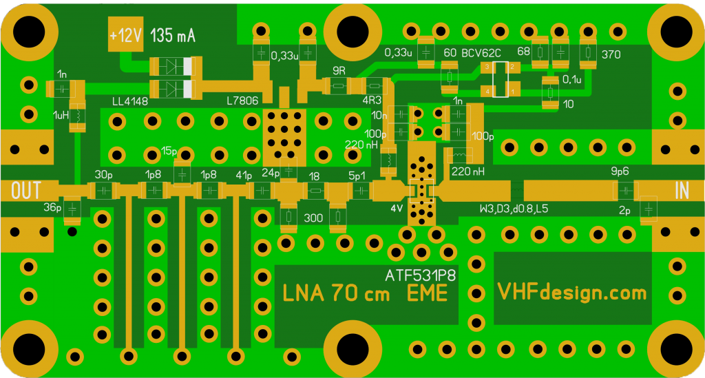
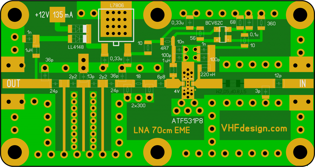
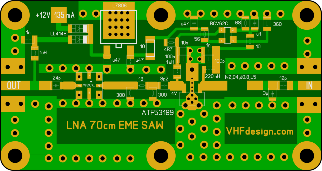
LNA 70 cm EME was manufactured based on ATF-531P8, regulating and tested. Comparison of the noise figure measurements using EME antenna of the LNA based on ATF-531P8 and LNA based on SAV-541+ (ATF-54143) shows the same characteristics (the noise of the sun relatively to the cold sky).
NF measurements results calculation
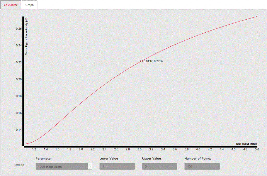
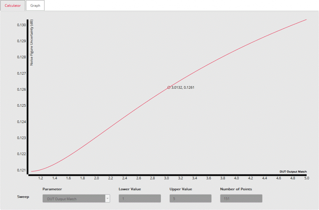
A separate question – NF measurements errors, that caused with high input VSWR. Here is an interesting online calculator, that allow to calculate the possibilities of different noise generators and take care of measurements uncertainty. Lets take ИКШ 8970B with 346A noise generator, with NF = 0.3dB and Gain = 20dB, measurements error can be +- 0.12dB. This calculator allow to output measurements error graph as a function (for example LNA input and output VSWR). Here is possible measurements input errors. Obviously, with VSWR = 3 measurements error can be +- 0.22dB. LNA measurements uncertainty depends of LNA gain and with Gain > 20dB its not too much (with VSWR = 3 it is +- 0.13 dB).
Conclusions:
- The absolute value measurements of the low noise figure is a problem using noise figure analyzer. The best industrial NF analyzer of the PSA series has the main error equals +/-0.083 dB with noise generator N4000 series.
- Comparing of the two LNA with equal NF but different VSWR we measure different NF values.
- The sole final criteria of the noise figure EME LNA estimation is relative measurement of the “cold sky” noise to the noise of the sun (or other space noise sources).
- EME LNA with bad VSWR at the input is a standard (unfortunately compelled). Reflections from the LNA input leads to moderate reduction of the receiver antenna gain, but does not lead to the loss of the NF (sensitivity)
The designed LNA is undisputed NF leader at the 2m band. For the 70cm band it is identical to LNA based on SAV-541+, but it has better dynamic range and maximum allowable power at the input. The excellent suppression BPF in out of the pass-band in combination with high OIP3 allows using LNA in the city with close distance broadcast FM and TV transceivers. This is the best 2m LNA solution that we can offer at this moment.
LNA 2m ATF531 N-female
| Name | LNA-2m-ATF531-N-female |
| Based on | ATF-53189 |
| Gain | > 26 dB |
| NF | < 0.3 dB at 144 MHz |
| OIP3 | 37 dBm |
| Filter BW (-3 dB) | < 15 MHz |
| P input (max) | 24 dBm |
| Supply operation | 12 V & 140 mA |
| Impedance | 50 Ohm |
| RF connectors | N-female |
| Dimensions | 72 x 43 x 20 mm (w/o connectors) |
| Weight | 0.15 kg |
| 1 | x | LNA-2m-ATF531-N-female |
LNA 70cm ATF531 SAW filter N-female
| Name | LNA-70cm-ATF531-SAW-N-female |
| Based on | ATF-53189 |
| Gain | > 22 dB |
| NF | < 0.4 dB at 432 MHz |
| OIP3 | 37 dBm |
| Filter BW (-3 dB) | < 20 MHz |
| P input (max) | 24 dBm |
| Supply operation | 12 V & 140 mA |
| Impedance | 50 Ohm |
| RF connectors | N-female |
| Dimensions | 72 x 43 x 20 mm (w/o connectors) |
| Weight | 0.15 kg |
| 1 | x | LNA-70cm-ATF531-SAW-N-female |
General inquiries:
![]() admin@vhfdesign.com
admin@vhfdesign.com
Technical support:
![]() us4ici@vhfdesign.com
us4ici@vhfdesign.com
Check the availability:
https://vhfdesign.com/kits/list
